P04 2004
When I first designed P04, It was around 1998 my senior year in high school. But I actually modeled the car when I started using rhino, some early 2000s. Car had a basic pre-WWII shape giving it a classic look yet it had some modern features on it such as ground effects. Today, I have just made a simplified CFD model of the car in about 2 hours time and have a 150 iteration run in Ansys CFD software. Results are not perfectly accurate to real world but they are close, such as lowest convergence achieved was around 2.8156e-2 (0.028156%).
Since I am unemployed I thought I go back and evaluate my old designs just to see how well I would have done as a 20 year old me (in this experiment I used a 2004 model of P04 so I was 23year old when I designed it). P04 was designed to be a medium speed sports car not an high end sports car. I was heavily inspired from Morgan Aero 8 (1996 version) and Panoz Esperante GTR-1 while designing it yet it is not completely look a likes of those two cars.
CFD model is was a simplified geometry of late 2004 model of P04 which have a relatively low nose and more realistic engine hood. 150 iterations run in Ansys CFD as a steady state mode. to avoid longer calculation time half model is used so results are based on the half model which need to be multiplied with 2.
Some of the reference values for the test was;
Wind And Ground Speed: 70 m/s (approx. 252kmh)
Frontal Area of the Car: 0.9274703 m^2 (2*0.9274703=1.8549406 m^2 total frontal area)
Rest of the parameters were set according to Ansys CFD sheets which can be found in Program website and over the internet (IF you would like to have full set up parameters you may email or message me).
As a result;
Drag (Half Model Results) :
Forces - Direction Vector (0 1 0)
Forces (n) Coefficients
Zone Total Total
bodywork 740.54741 0.26604117
undertray 77.840038 0.027963983
wall-solid 253.42488 0.091042722
------------------------- --------------- ---------------
Net 1071.8123 0.38504788
Total Drag Generated (complete model) :2143.6246 N (~218.59 kg-f or 481.91 lb-f) at 252 kmh.
Y direction is the direction of drag which is a long the length of the car.
Lift (Half Model Results) :
Forces - Direction Vector (0 0 1)
Forces (n) Coefficients
Zone Total Total
bodywork 2191.7282 0.78737692
undertray -2875.6599 -1.0330789
wall-solid -40.74762 -0.014638556
------------------------- --------------- ---------------
Net -724.67929 -0.26034056
Total Lift generated (complete model): -1449.35858 N (~ -147.8 kg-f or -325.8lb-f) at 252 kmh. Z direction is the direction of lift.
Calculated lift to drag ratio: -0.676:1
Moment of lift is rear wards. moment center of the model is; Moment Center according to coordinates axis of X,Y,Z (0, 2.15, 0.36) Moment Axis (1, 0, 0). which is the point that intersects at center of the wheelbase along Z axis and Z height of component of the volume centroid.
Total moment of lift is equal to 1950.7951 N-m which is in positive direction. In other word rear of the car generates more down force than the front of the car. Direction of the moment is actually determined by the under tray of the car which plays a big role in downforce generation. Aerodynamic balance of the bodywork is actually forward biased.
From these findings we can say that car generates quite a bit drag probably a little higher than now a days sports cars but it generates quite good amount of downforce especially at the rear of the car.
And Finally some Images from the CFD test:
P04 R 2004
Racing version of P04 was designed several months earlier than then the road going version (end of 2003). I must say I do have an obsession with racing cars that looks like road cars. P04 road version was designed based on the racing version with slightly less frontal area. Road version was narrower obviously and had slightly higher cockpit height. Racing version had two different cooling configurations yet one was made for rendering and the other was for the analysis. I never had an access to a analysis program back then. So all my designs were experimental until Galmer GT (my first ever design tested with a CFD program).
1. configuration: Side Mounted Radiators; As I have mention car was very much inspired from Panoz GTR-1 for its layout so I made a version with side mounted radiators, where radiators were mounted inside the side pods behind the front wheel. two ducts were feeding those radiators and exhausting from side. Front splitter opening were supplying cool air to the engine bay exhausting partially from forward of wind shield and side pod openings to the rear wheel that's why rear wheel arches are kind of oversized. There also was an opening that supplies air to the radiators front the front splitter opening. I don't know how functional it is but I will be testing it when I have an access to an CFD program.
2. configuration: Front Mounted Radiators; Front bonnet is slightly higher on this version and front wheel poontoons are more of a tear drop shape from top view. This configuration is also very much similar with the road version.
Differences between race version and the road versions;
Front overhang is 50 mm shorter on the racing versions.
Tail angle (Average) is 4 degrees more on the racing versions.
Tail width is slightly less on the racing versions.
Cockpits are 30 mm lower on the racing versions.
Racing versions are 50 mm wider than the road version
Side pods are significantly higher on the racing versions
A pillar start points are more forward on the racing versions.
As for the CFD Test I have run 500 iteration steady state test with same conditions that I have run on the road version. Model detail is more on the racing version so I was expecting a higher drag due to fully functioning radiator inlets and more detailed wheels.
Results for the racing version:
Test was also carried on at 70 m/s and Frontal area of the racing version is 1.94 m^2 excluding mirrors. Same configuration was applied for the solution such as moving ground and rotating wheels. and half model was considered for the calculation.
Regions of the model:

Drag (Half Model Results) :
Forces - Direction Vector (0 1 0)
Forces (n) Coefficients
Zone Total Total
body_work 616.21496 0.21223392
front_diffuser 30.942650 0.010657125
front_wheels 107.03279 0.036863739
rear_diffuser 151.49492 0.052177181
rear_wheels 110.02186 0.037893223
rear_wing 82.972048 0.02857685
undertray 18.214005 0.0062731838
wall-solid 250.88716 0.088219749
------------------------- --------------- ---------------
Net 1373.0367 0.47289497
Total Drag Generated (complete model) :2746.0734 N (~280.022 kg-f or 617.342 lb-f) at 252 km/h.
Y direction is the direction of drag which is a long the length of the car.
Total Lift generated (complete model): -8134.1454 N (~ -829.452 kg-f or -1828.63 lb-f) at 252 kmh. Z direction is the direction of lift.
Calculated lift to Drag ratio: -2.9621:1
Honestly I wasn't expecting this much of a lift to drag ratio from this car. there are few faulty areas that needs to be fixed though. car generates high drag which can be reduced and at the end of the front diffuser where it joins with main floor there are pressure zones that possibly create lift and front diffuser looses its efficiency because of that. I think P04 would have been an interesting looking race car, rather than looking modern sports car it looks like 1930s cars after all and it has pretty good lift to drag ratio.
When I first designed P04, It was around 1998 my senior year in high school. But I actually modeled the car when I started using rhino, some early 2000s. Car had a basic pre-WWII shape giving it a classic look yet it had some modern features on it such as ground effects. Today, I have just made a simplified CFD model of the car in about 2 hours time and have a 150 iteration run in Ansys CFD software. Results are not perfectly accurate to real world but they are close, such as lowest convergence achieved was around 2.8156e-2 (0.028156%).

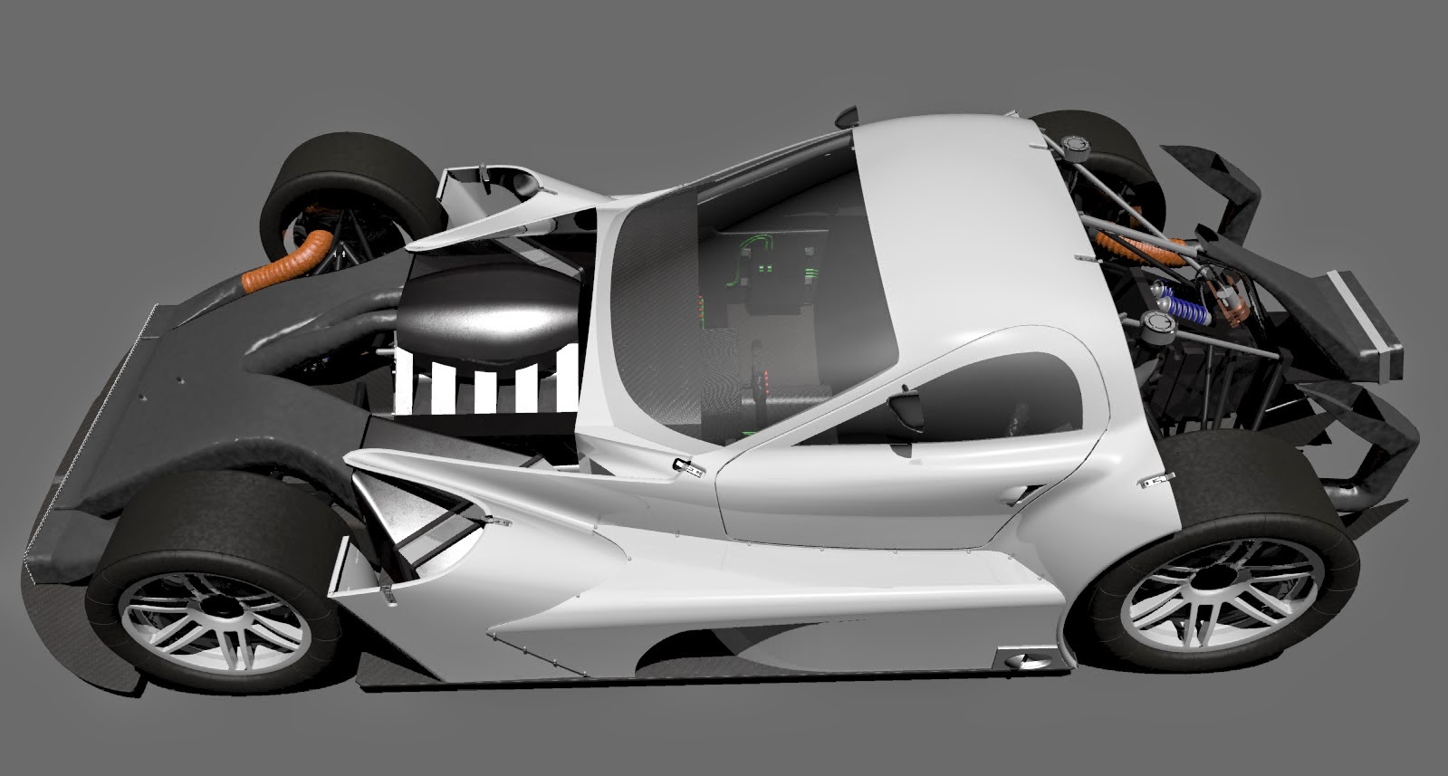
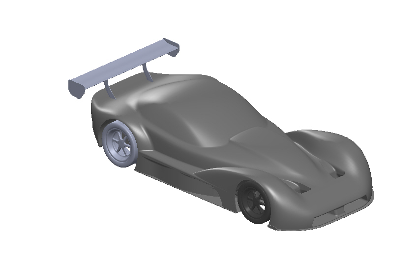
 |
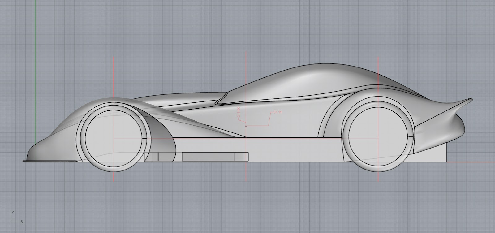
| detailed rendering of base model used for CFD test |
 |
| detailed rendering of base model used for CFD test |
 |
| detailed rendering of base model used for CFD test |
Since I am unemployed I thought I go back and evaluate my old designs just to see how well I would have done as a 20 year old me (in this experiment I used a 2004 model of P04 so I was 23year old when I designed it). P04 was designed to be a medium speed sports car not an high end sports car. I was heavily inspired from Morgan Aero 8 (1996 version) and Panoz Esperante GTR-1 while designing it yet it is not completely look a likes of those two cars.
CFD model is was a simplified geometry of late 2004 model of P04 which have a relatively low nose and more realistic engine hood. 150 iterations run in Ansys CFD as a steady state mode. to avoid longer calculation time half model is used so results are based on the half model which need to be multiplied with 2.
Some of the reference values for the test was;
Wind And Ground Speed: 70 m/s (approx. 252kmh)
Frontal Area of the Car: 0.9274703 m^2 (2*0.9274703=1.8549406 m^2 total frontal area)
Rest of the parameters were set according to Ansys CFD sheets which can be found in Program website and over the internet (IF you would like to have full set up parameters you may email or message me).
As a result;
Drag (Half Model Results) :
Forces - Direction Vector (0 1 0)
Forces (n) Coefficients
Zone Total Total
bodywork 740.54741 0.26604117
undertray 77.840038 0.027963983
wall-solid 253.42488 0.091042722
------------------------- --------------- ---------------
Net 1071.8123 0.38504788
Total Drag Generated (complete model) :2143.6246 N (~218.59 kg-f or 481.91 lb-f) at 252 kmh.
Y direction is the direction of drag which is a long the length of the car.
Lift (Half Model Results) :
Forces - Direction Vector (0 0 1)
Forces (n) Coefficients
Zone Total Total
bodywork 2191.7282 0.78737692
undertray -2875.6599 -1.0330789
wall-solid -40.74762 -0.014638556
------------------------- --------------- ---------------
Net -724.67929 -0.26034056
Total Lift generated (complete model): -1449.35858 N (~ -147.8 kg-f or -325.8lb-f) at 252 kmh. Z direction is the direction of lift.
Calculated lift to drag ratio: -0.676:1
Moment of lift is rear wards. moment center of the model is; Moment Center according to coordinates axis of X,Y,Z (0, 2.15, 0.36) Moment Axis (1, 0, 0). which is the point that intersects at center of the wheelbase along Z axis and Z height of component of the volume centroid.
 | ||
| Above image shows the moment center of the car graphically |
Total moment of lift is equal to 1950.7951 N-m which is in positive direction. In other word rear of the car generates more down force than the front of the car. Direction of the moment is actually determined by the under tray of the car which plays a big role in downforce generation. Aerodynamic balance of the bodywork is actually forward biased.
From these findings we can say that car generates quite a bit drag probably a little higher than now a days sports cars but it generates quite good amount of downforce especially at the rear of the car.
And Finally some Images from the CFD test:
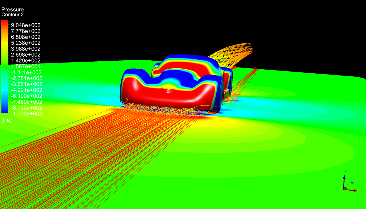
 |
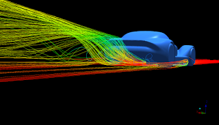
| Pressure gradients of the bodywork (-1000Pa to 1000Pa) and streamlines along the floor. |
 |
| Streamlines along the floor |
 |
| Pressure gradients on the bodywork |
 |
| Pressure zone around the car |
 |
| Vortex regions |
 |
| Vortex regions |
 |
| Stream lines along the floor |
P04 R 2004
Racing version of P04 was designed several months earlier than then the road going version (end of 2003). I must say I do have an obsession with racing cars that looks like road cars. P04 road version was designed based on the racing version with slightly less frontal area. Road version was narrower obviously and had slightly higher cockpit height. Racing version had two different cooling configurations yet one was made for rendering and the other was for the analysis. I never had an access to a analysis program back then. So all my designs were experimental until Galmer GT (my first ever design tested with a CFD program).
1. configuration: Side Mounted Radiators; As I have mention car was very much inspired from Panoz GTR-1 for its layout so I made a version with side mounted radiators, where radiators were mounted inside the side pods behind the front wheel. two ducts were feeding those radiators and exhausting from side. Front splitter opening were supplying cool air to the engine bay exhausting partially from forward of wind shield and side pod openings to the rear wheel that's why rear wheel arches are kind of oversized. There also was an opening that supplies air to the radiators front the front splitter opening. I don't know how functional it is but I will be testing it when I have an access to an CFD program.
 |
| Side mounted radiators configuration |
2. configuration: Front Mounted Radiators; Front bonnet is slightly higher on this version and front wheel poontoons are more of a tear drop shape from top view. This configuration is also very much similar with the road version.
 |
| Front mounted radiators configuration |
Differences between race version and the road versions;
Front overhang is 50 mm shorter on the racing versions.
Tail angle (Average) is 4 degrees more on the racing versions.
Tail width is slightly less on the racing versions.
Cockpits are 30 mm lower on the racing versions.
Racing versions are 50 mm wider than the road version
Side pods are significantly higher on the racing versions
A pillar start points are more forward on the racing versions.
As for the CFD Test I have run 500 iteration steady state test with same conditions that I have run on the road version. Model detail is more on the racing version so I was expecting a higher drag due to fully functioning radiator inlets and more detailed wheels.
Results for the racing version:
Test was also carried on at 70 m/s and Frontal area of the racing version is 1.94 m^2 excluding mirrors. Same configuration was applied for the solution such as moving ground and rotating wheels. and half model was considered for the calculation.
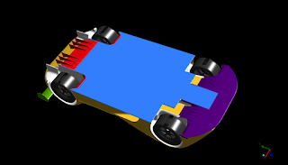
Regions of the model:
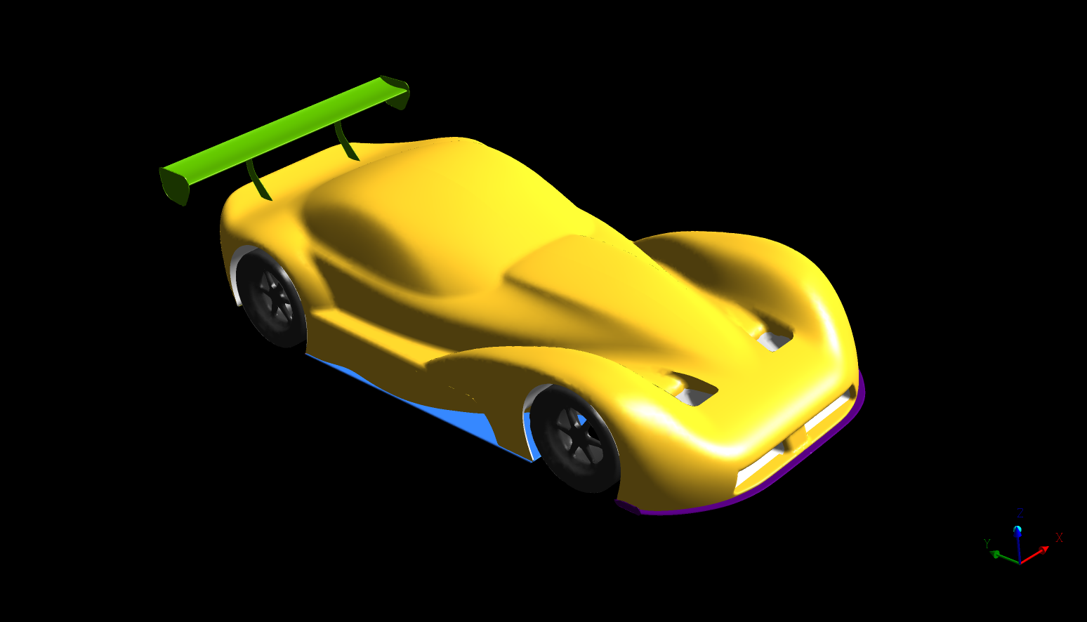
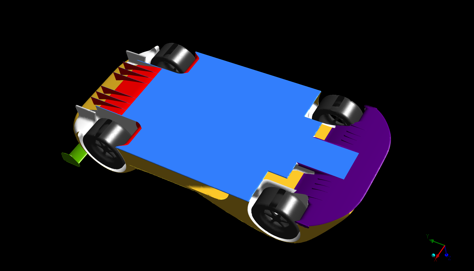
Yellow: Bodywork
Green: Rear win assy.
Blue: Flat under tray
Purple: Front splitter (diffuser)
Red: Read diffuser
White: Solid wall boundaries and misc.
Dark Gray: Wheels (calculated separately)
Drag (Half Model Results) :
Forces - Direction Vector (0 1 0)
Forces (n) Coefficients
Zone Total Total
body_work 616.21496 0.21223392
front_diffuser 30.942650 0.010657125
front_wheels 107.03279 0.036863739
rear_diffuser 151.49492 0.052177181
rear_wheels 110.02186 0.037893223
rear_wing 82.972048 0.02857685
undertray 18.214005 0.0062731838
wall-solid 250.88716 0.088219749
------------------------- --------------- ---------------
Net 1373.0367 0.47289497
Total Drag Generated (complete model) :2746.0734 N (~280.022 kg-f or 617.342 lb-f) at 252 km/h.
Y direction is the direction of drag which is a long the length of the car.
Lift (Half Model Results) :
Forces - Direction Vector (0 0 1)
Forces (n) Coefficients
Zone Total Total
body_work 2457.7375 0.84648261
front_diffuser -1559.5129 -0.53712024
front_wheels 105.76402 0.036426757
rear_diffuser -505.90182 -0.17424037
rear_wheels 82.35793 0.028365339
rear_wing -1712.1224 -0.5896813
undertray -2336.1731 -0.80461397
wall-solid -599.22192 -0.20638125
------------------------- --------------- --------------- --------------- --------------- --------------- ---------------
Net -4067.0727 -1.4007624
Total Lift generated (complete model): -8134.1454 N (~ -829.452 kg-f or -1828.63 lb-f) at 252 kmh. Z direction is the direction of lift.
Calculated lift to Drag ratio: -2.9621:1
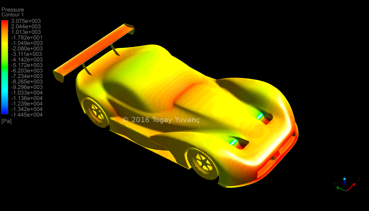 |
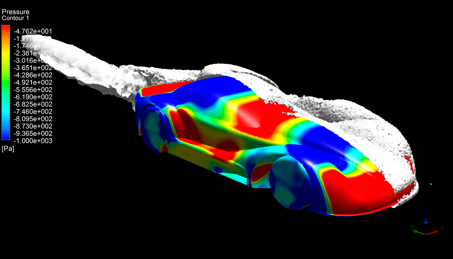
| Pressure Contours |
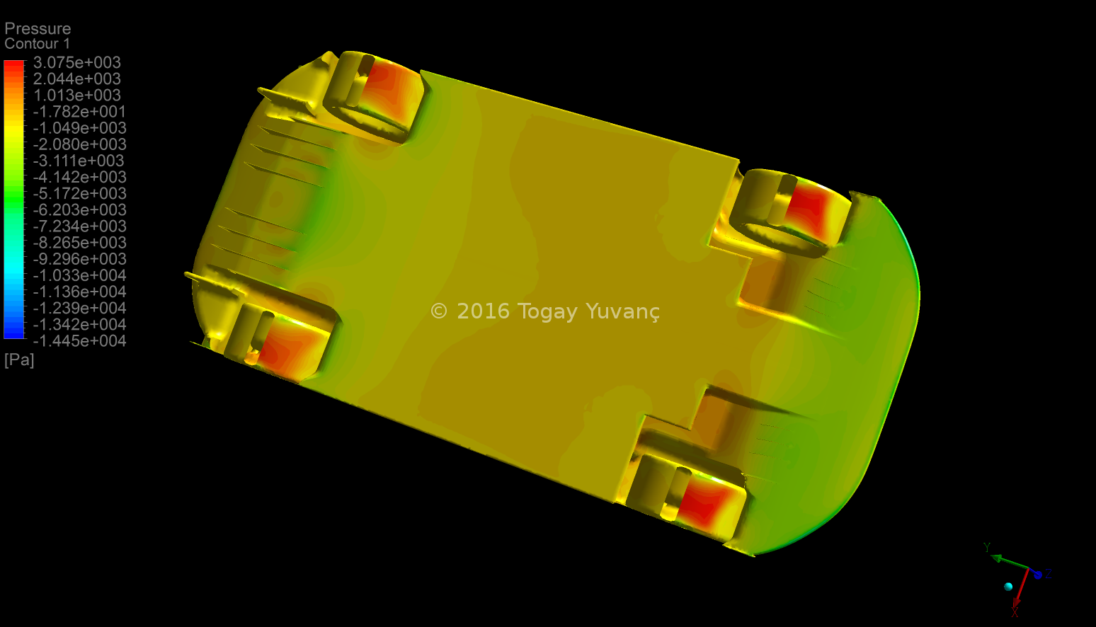 |
| Pressure Contours |
 |
| Stream lines |
 |
| Stream lines |
 |
| Stream lines |
Honestly I wasn't expecting this much of a lift to drag ratio from this car. there are few faulty areas that needs to be fixed though. car generates high drag which can be reduced and at the end of the front diffuser where it joins with main floor there are pressure zones that possibly create lift and front diffuser looses its efficiency because of that. I think P04 would have been an interesting looking race car, rather than looking modern sports car it looks like 1930s cars after all and it has pretty good lift to drag ratio.
© 2016 Togay Yuvanç
No comments:
Post a Comment